Turning a Dumb AC Unit Smart (Without Losing my Security Deposit)
TL;DR: DIY home automation is ezpz with nothing more than a stepper motor, an esp32, and a high tolerance for Jank.
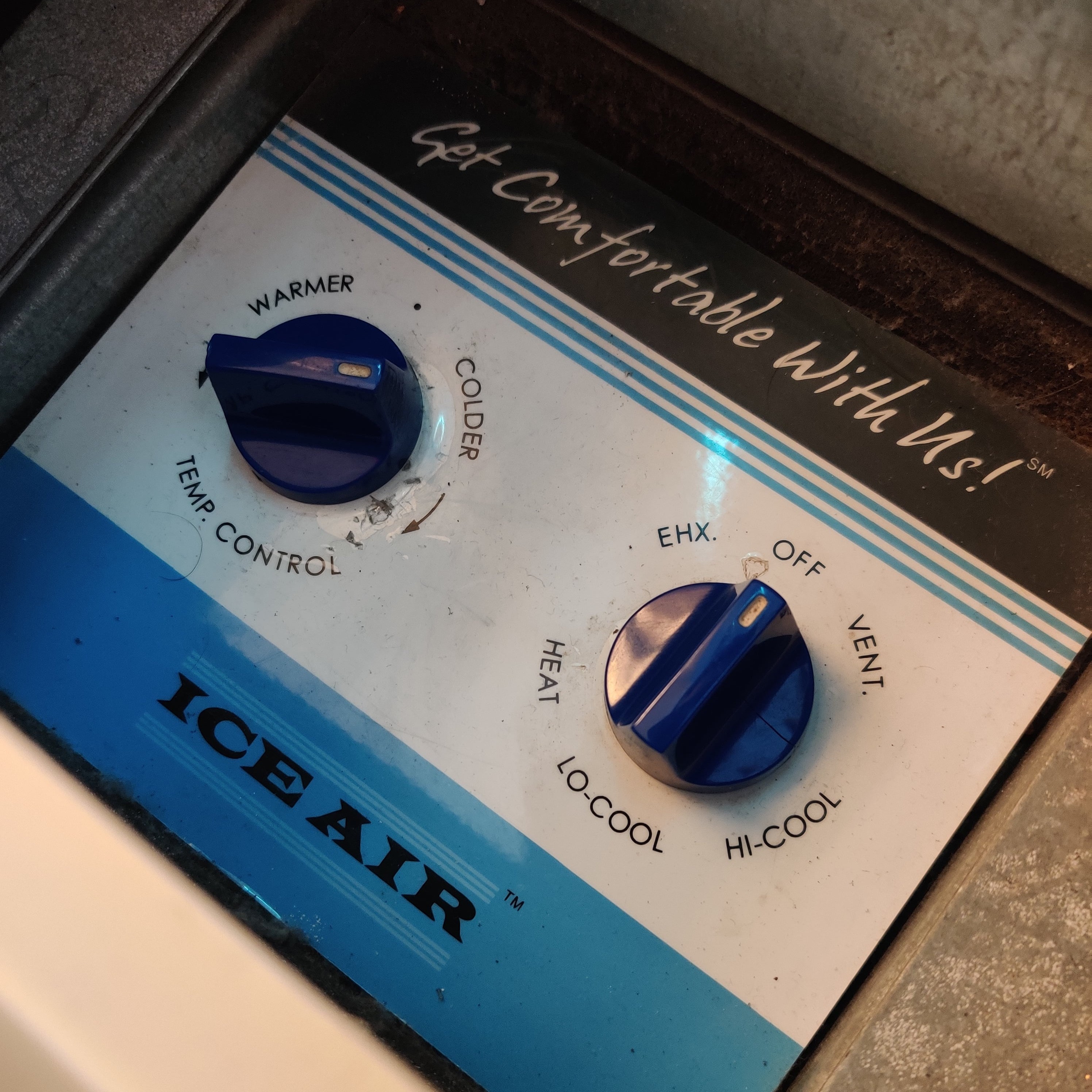
My rental apartment’s AC unit can only be controlled using these retro-looking analog knob-based controls, mounted right onto the unit. No separate wall-mounted thermostat, no remote control… nothin’ fancy whatsoever.
These knobs work… but having to constantly stand up and fiddle with them gets annoying pretty quick.
Fortunately, there’s an ‘ol Prilik family saying that goes something like this: “remember son - the hardest problems in life can usually be solved with nothing more than a stepper motor, an esp32, and a dream”1
And sure enough, after dropping ~$15 on parts, waiting for things to arrive from China, and spending a few hours iterating on the hardware assembly and firmware… I hacked together this beautiful mess:
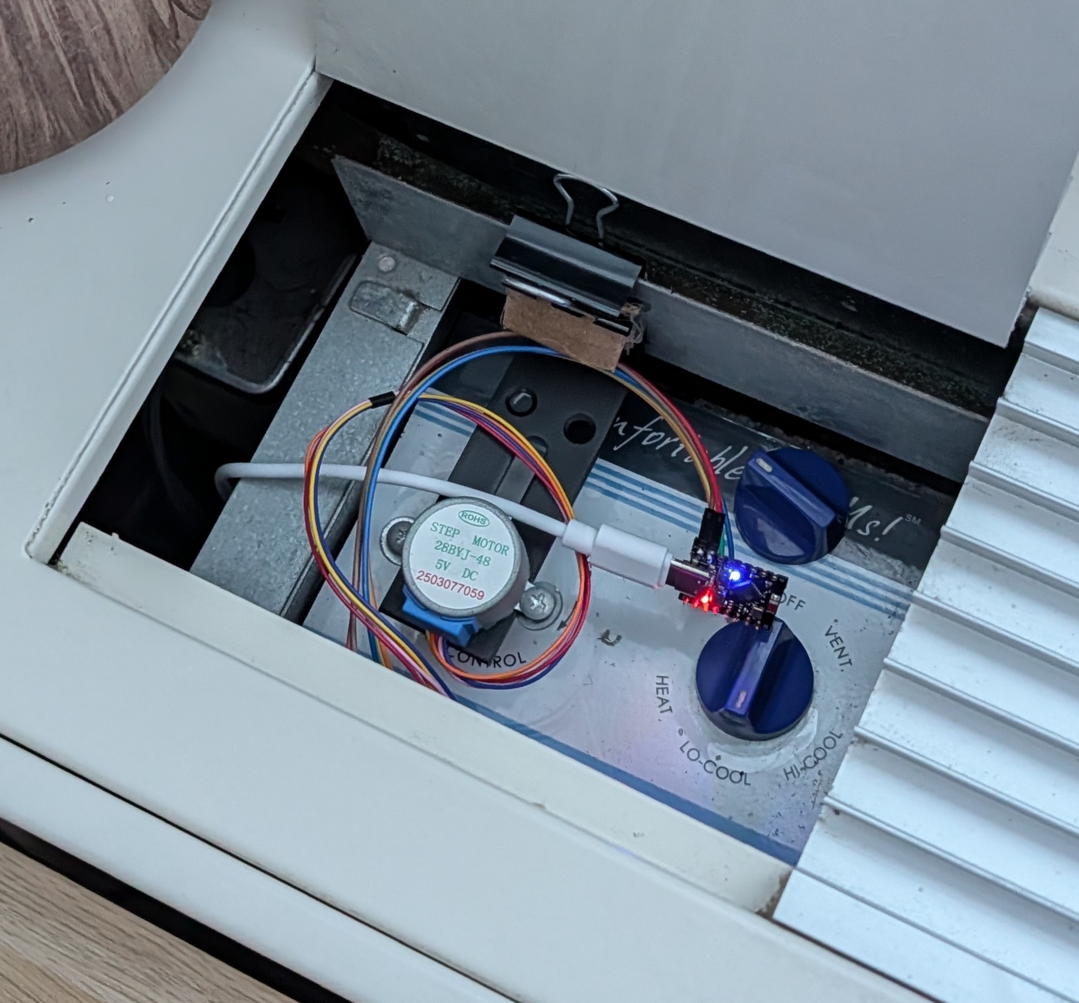
What you’re looking at here is a jerry-rigged esp32-controlled stepper motor, coupled to one of my AC unit’s knobs using a shaft coupler, all affixed to the AC’s back-plane using a cheap L-bracket and a binder clip (with some industrial-grade cardboard padding for good measure).
This whole MacGyver’d up contraption talks to my Home Assistant instance over MQTT, which turns the AC unit on/off based on the state of a temperature sensor located in the same room.
Et voila 🪄 ✨
Just like that - I’ve managed to free myself from the shackles of having to get up off the couch just to tweak my AC!
For all you professional embedded and mechatronics folks out there: I strongly suggest you stop reading here.
The rest of this blog post is a walkthrough of a software engineer’s approach to home automation and building custom hardware, and let me tell you: both the final product, and the journey to get there, are hella jank.
That said… if you’re not afraid of a bit of jank: read onwards, and join me on this fun foray into how I managed to hack together some totally bespoke home-automation hardware with almost no budget, or experience!
🗽 Setting the stage⌗
In April 2025, I moved to New York City. After a brief apartment hunt, I managed to find a place I’m pretty happy with: the location is convenient, the building is fairly modern, and the rent is an absolute steal. There’s not much to complain about!
…well, except for the AC situation.
See, for whatever reason, developers in NYC really like using these loud, power-hungry, wall-mounted PTAC units in their apartment buildings. Some buildings might spend a bit extra in order to wire these units up to wall-mounted thermostats… but oftentimes, they’ll just go with the cheapest option: completely analog, unit-mounted knobs.
Here’s a picture of what I’m talking about:
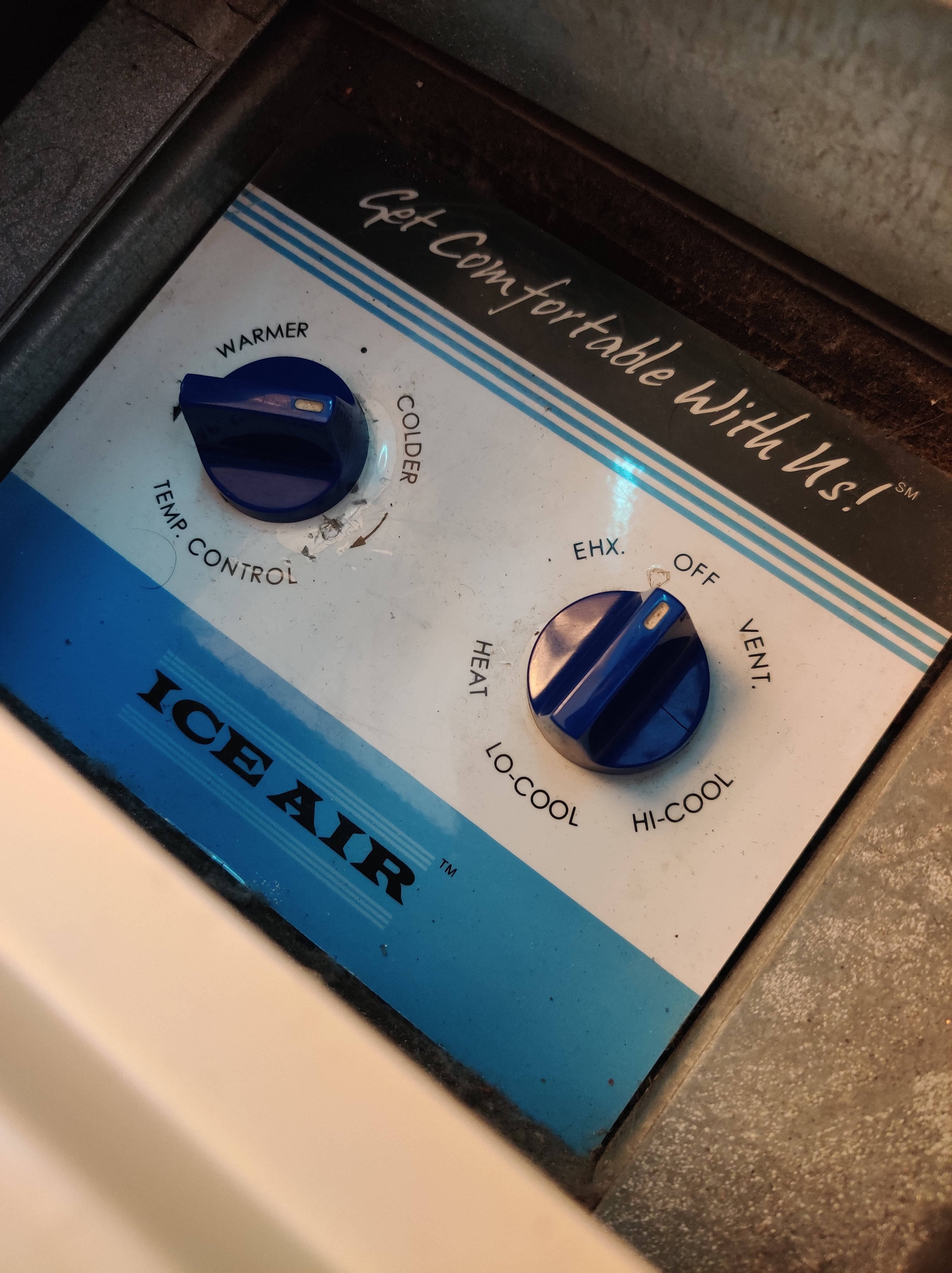
Yeah - guess which option my building went with 🙃
🤔 What are my options here?⌗
Like any good renter, the first thing I did was gently ask my landlord if there was any way to “upgrade” the controls to something a bit more… modern. As expected, the response was roughly along the lines of “lol no, why would we do that?”, which, to be fair, was basically the response I expected.
Well, no matter, like any good engineer - surely I can hack my way out of this pickle?
After a bit of finessing, I managed to pop the cover off the unit, and expose its soft underbelly inner workings. Much to my surprise, not only did I find some info about the unit, but even a whole wiring diagram!
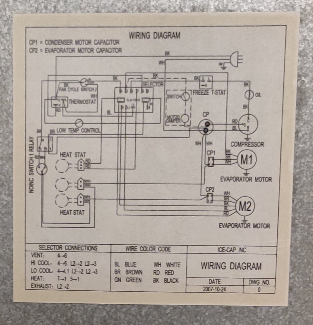
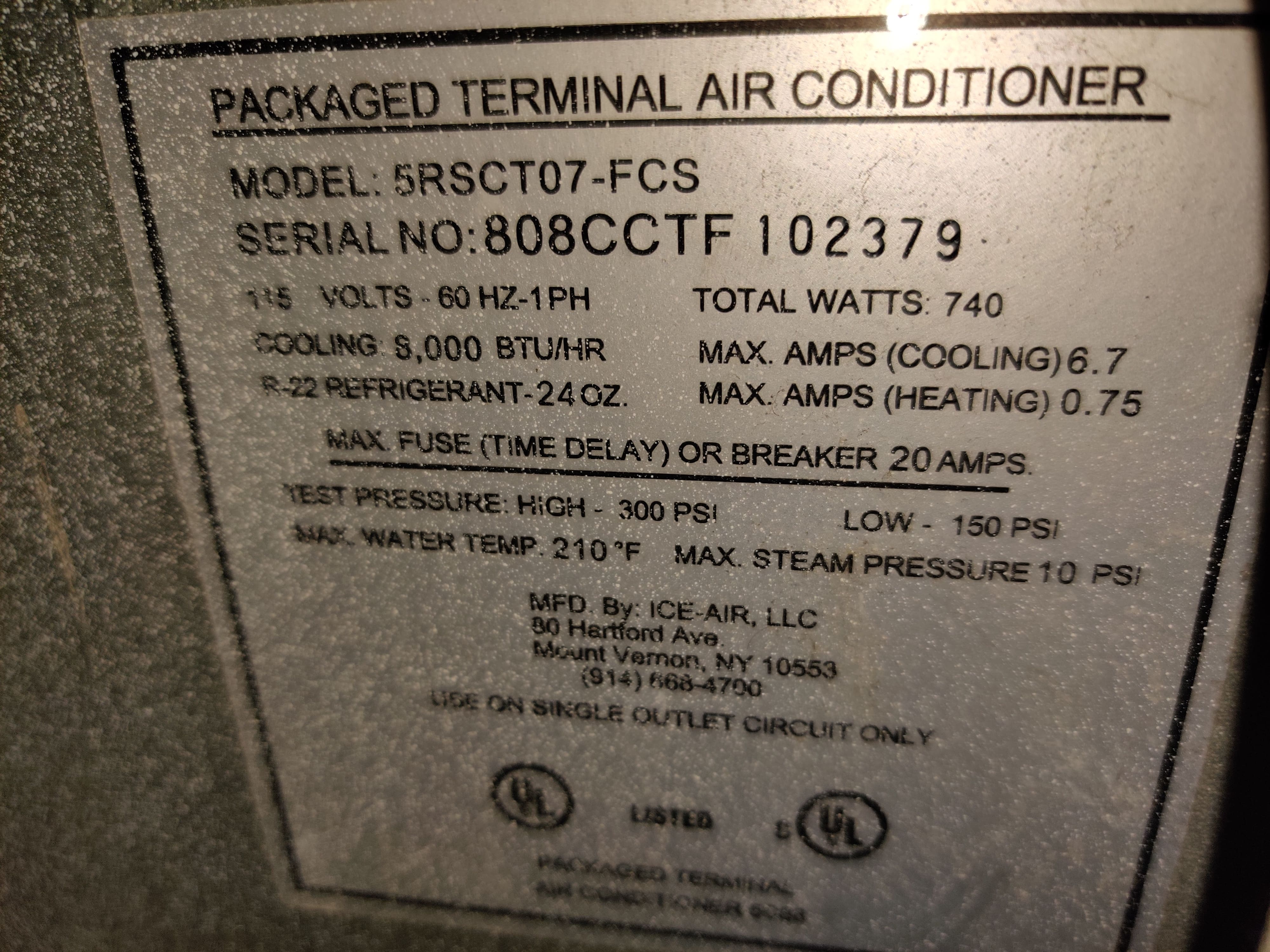
Now, I’m no expert when it comes to wiring diagrams, but by following the wiring, it certainly seems like this entire circuit is operating at line voltage, with nary a low-voltage digital signal I can hook into in sight.
⏺️ Smart Relays?⌗
Ok, maybe I can just splice in a smart relay somewhere? I’m no electrician, but it’s probably not that hard, right?
Well, maybe?
But honestly, I didn’t think this was gonna be a viable route for me.
Setting aside the fact that working with line voltage and HVAC equipment is a bit “spooky” for someone with zero electrical wiring experience (and that my landlord probably wouldn’t be thrilled with me messing about with these sorts of things), the bigger issue was that all the juicy wires I’d be interested in intercepting are stuffed deep inside the AC unit.
As far as I could tell, the only way to access those wires would be to yank the whole unit out of the wall… something that I wasn’t particularly interested in doing. This thread from ~2017 reinforced my impressions that this would be far more trouble than its worth.
So… what now?
🔌 Smart Plugs?⌗
Ok, here’s an idea: what if I just cut power to the unit using a smart plug?
Note: The internet was quick to warn me that toggling power to a running AC unit could potentially cause damage to the unit, especially if something goes wrong and you start rapidly cycling it on/off.
While I’m no expert in these sorts of things… for the sake of science (and because I’m a bit stubborn), I nonetheless kept looking into this option.
Alas, much to my chagrin - the unit plugs into the wall using one of those fancy NEMA 5-20P plugs, which is basically impossible to find a smart switch for!

Well shoot!
If hooking into the wiring is a non-starter, and putting the unit behind a smart plug is non-trivial… am I just out of luck?
Of course not!
Clearly it was time to put my engineering hat on and jank together a solution: why not just make a little robot to turn the dials for me?
🎛️ Dialing in the right approach⌗
Looking at the unit, we find 2 dials:
- Mode Control: A stiff, discrete dial, clicking between 6 “modes” of operation (Off, Lo-Cool, Hi-Cool2, Vent, Exhaust, and Heat)
- Temp Control: A smooth, analog dial, connected to a simple bimetallic-strip based thermostat
And fortunately - both plastic knobs pop right off, exposing a shaft that shouldn’t be too hard to mechanically couple with:
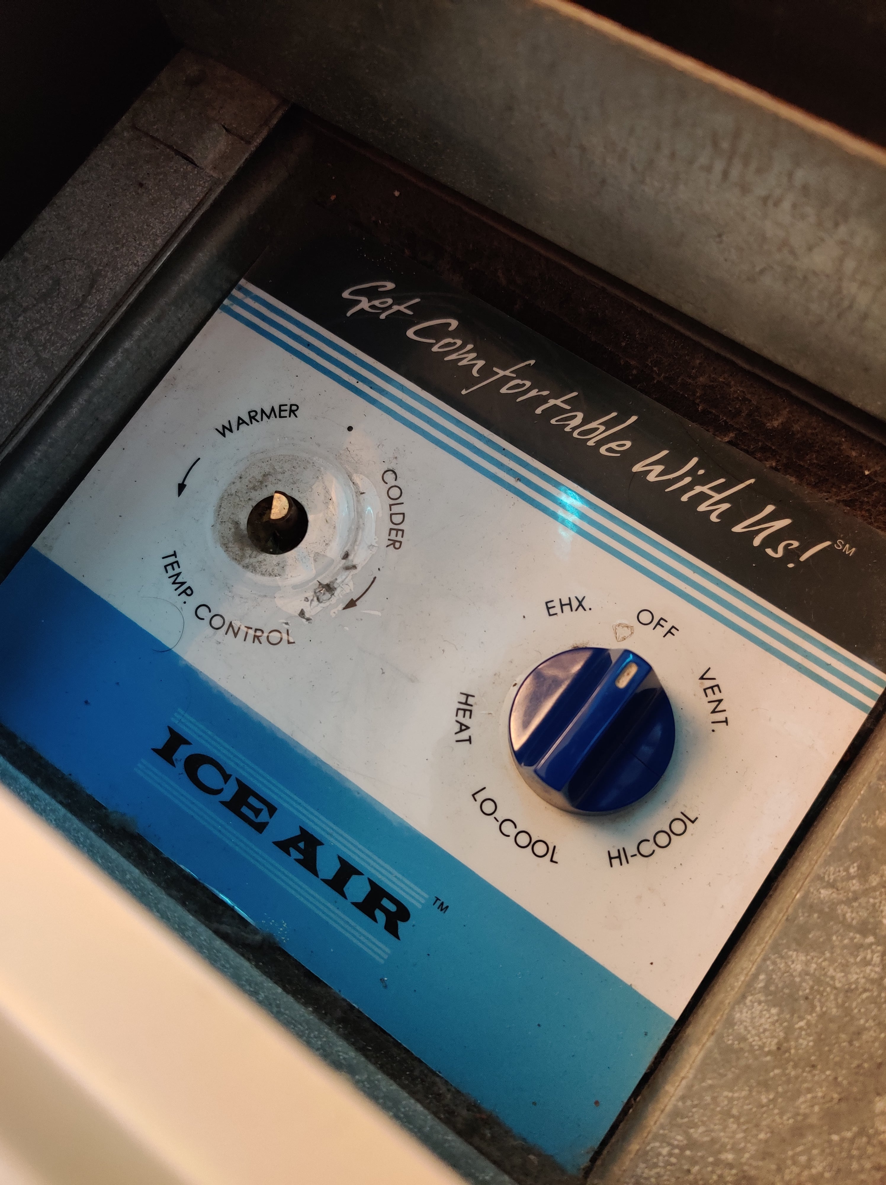
This gave me two options to toggle the AC unit on and off:
Option 1: hooking into the Mode Control dial
- Leave the Temp Control dial set to “max cold”
- Buy a stepper motor with enough torque to overcome the stiff action of the dial
- …which would probably need a 12V DC (if not more) power source, requiring extra circuitry to power
- …and require some more robust mounting hardware, to counteract the torque, and ensure the stepper motor stays in the right place
- Precisely calibrate the stepper motor to rotate the dial the right number of degrees between the “Off” state and the “Cool” state
Option 2: hooking into the Temp Control dial
- Leave the Mode Control dial on “Lo-Cool”3
- Buy a cheap, low-torque, low-power stepper motor, just powerful enough to rotate the fairly loose dial
- …that doesn’t need a lot of mounting hardware to stay in the right place, given that the torque is fairly low
- Imprecisely yeet the stepper motor all the way left/right, toggling the target temp between “really really hot” or “really really cold”
Hopefully you can guess which one I went with 🥰
Option 2 certainly is the “jankier” of the two options, given that it relies on a second-order property (target temp) to power the unit on/off… but hey - whatever’s easier, right?
🔨 The road to V0⌗
I was fairly sure this was gonna work, but obviously, the only way to find out was to hack together a proof-of-concept (ideally - with the least number of new purchases as possible).
To cut a long story short - here’s what I came up with for V0:
| Part | Cost | Source |
|---|---|---|
| ESP32 Dev Board | $6 | Amazon |
| Shaft Coupler | $6.69 | Amazon |
| Stepper motor + controllers | $2.66 ($8 / 3 pack) | Amazon |
| L Brackets | free | leftover ikea parts (from a LAIVA bookshelf) |
| screws | free | leftover monitor parts |
| USB Cable + charger | free | found in the ‘ol junk drawer |
Total: ~$16
And here’s the result:
(breadboard with the rest of the hardware out-of-frame)
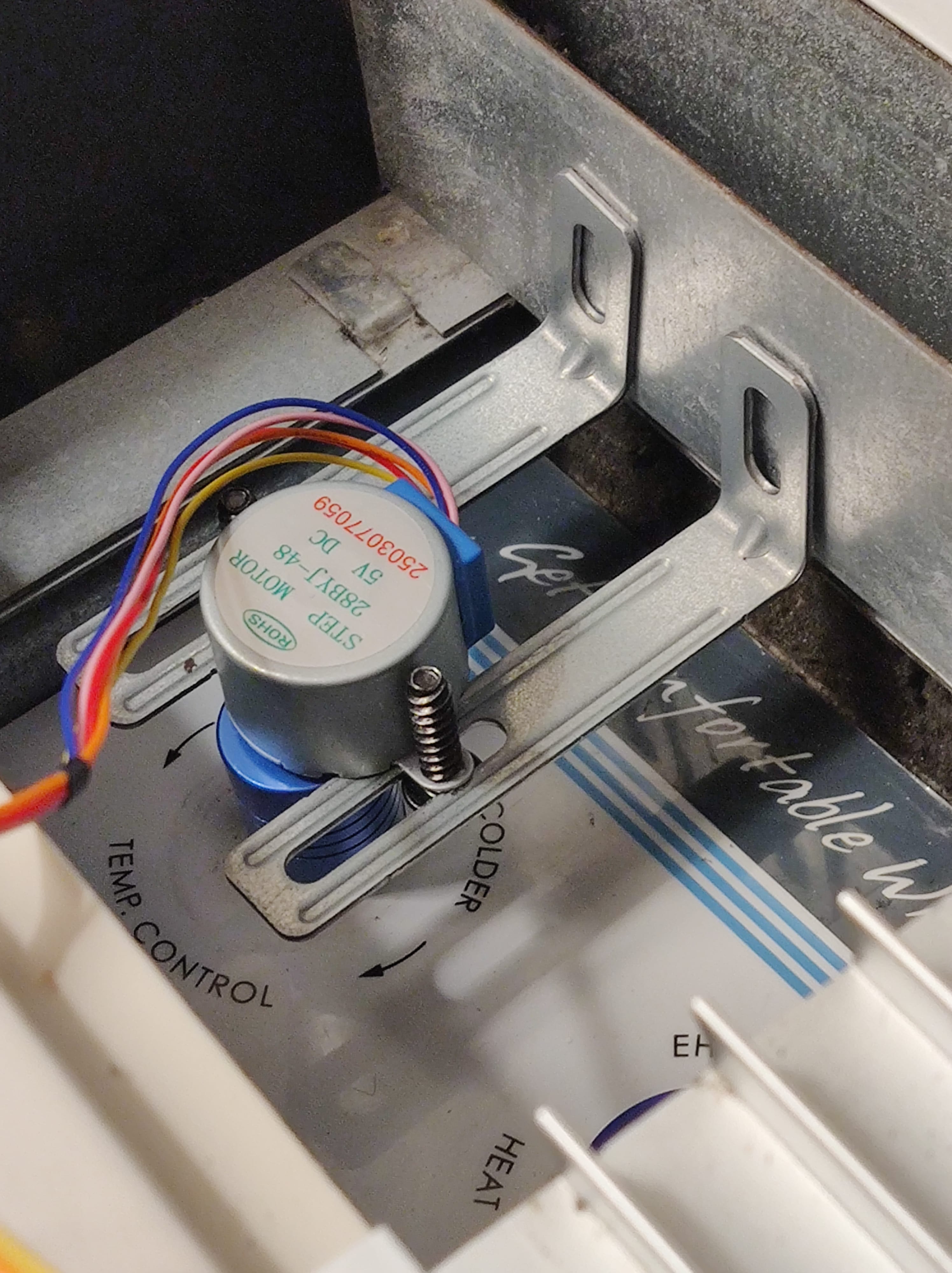
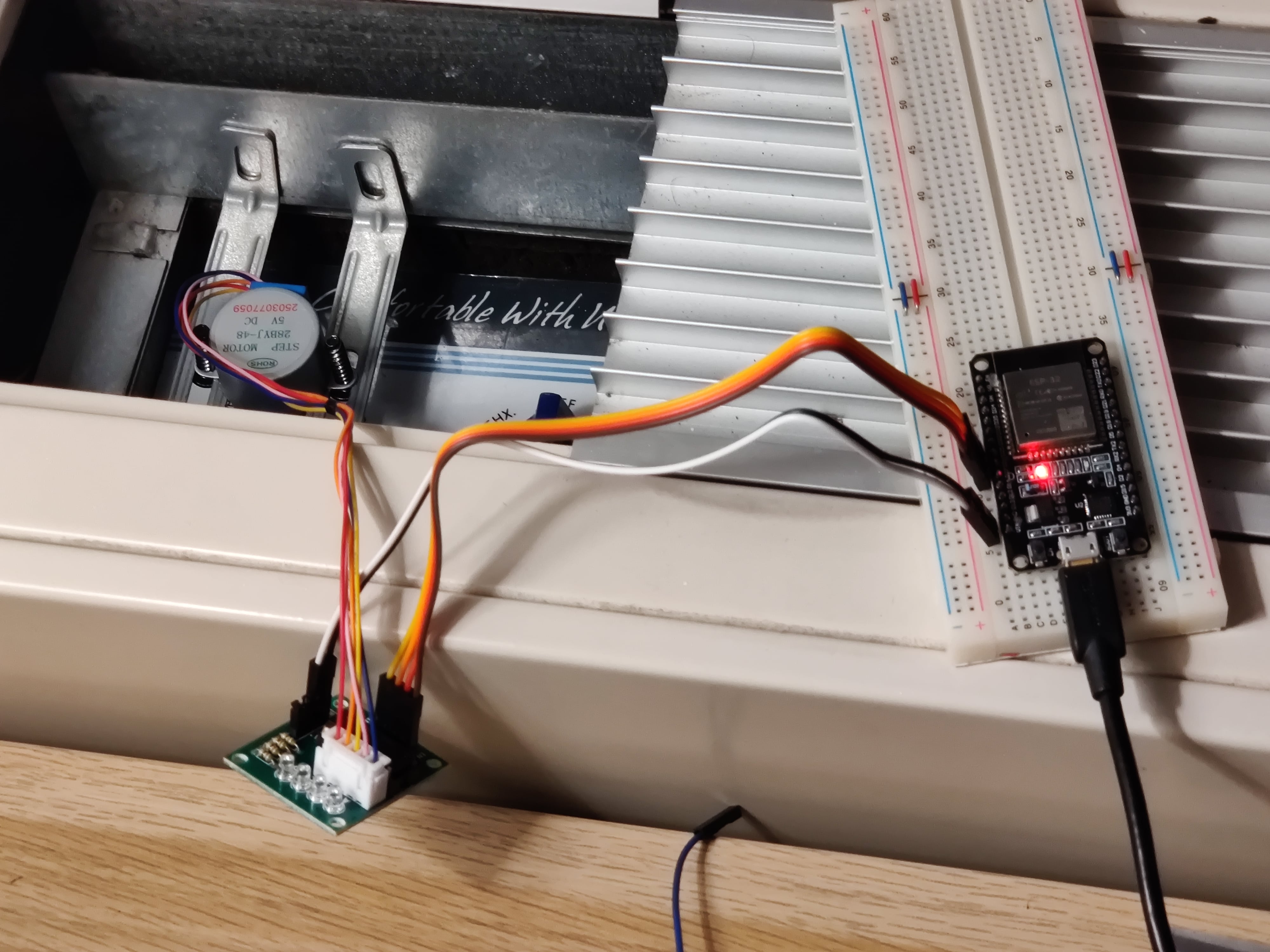
Since I couldn’t screw anything into the AC chassis (remember: security deposit!), I had to get creative. I ended up grabbing a couple of metal L-brackets left over from an IKEA LAIVA bookshelf, and some spare screws from a monitor VESA mount.
By bolting these to the stepper motor, it made the motor assembly physically “wider”. When the motor rotates, the brackets bump against the back wall of the control cavity, which resists the torque and forces the rotational energy down into the shaft coupler and turns the dial. Truly unintentional ingenious design!
Sidenote: I’m leaving out a few intermediate steps that I took to get to this design:
- I didn’t get the right shaft-coupler the first time (or the second time (or the third time…)), so it took a few Amazon returns until I found the right one.
- Before buying the ESP32 Dev Board, I validated the stepper motor + shaft coupler worked using a (really, really) old Arduino Leonardo I had lying around, and controlling it manually over serial (using a really long USB cable extending to my PC)
- My first attempt at mounting this thing involved wooden skewers, a glue stick, and a cut-up Amazon box… a failed experiment, to say the least.
Of course, what good is some hardware without some software?
💻 Writing the Firmware⌗
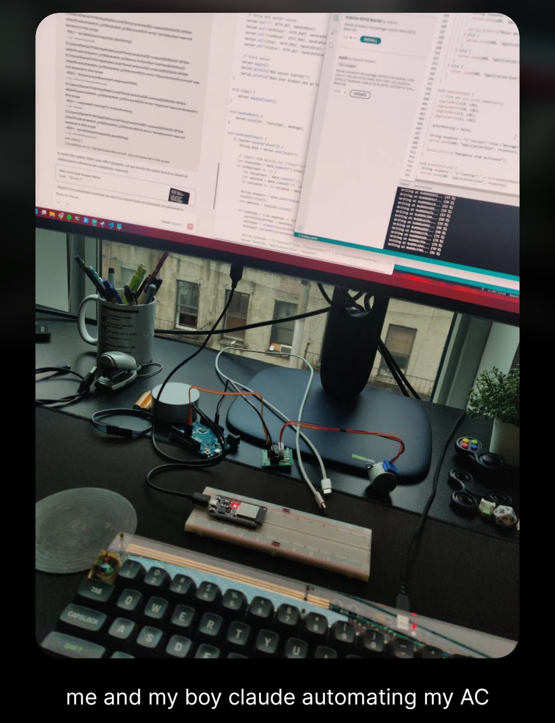
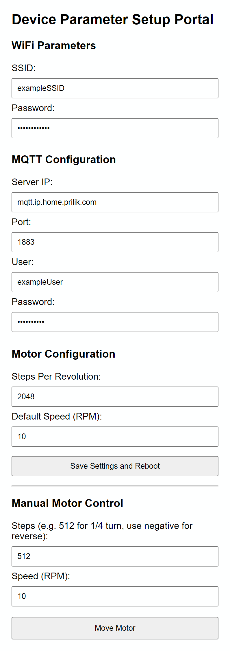
The firmware here is dead simple: it connects to Wi-Fi, hosts a local web server, and listens for HTTP/MQTT commands to spin the motor.
While I do somewhat miss the Good Old Days where I’d spend a couple weekends hacking together this sort of one-off firmware… truth be told, I’m kinda glad that LLMs can one-shot code for these sorts of projects. I ended up using a combo of Claude and Gemini, and they did a Totally Fine™️ job hacking together something that works.
It even generated a little Web UI I could use to configure my Wi-Fi credentials and adjust settings dynamically:
Code is available here, but honestly - it’s not all that interesting.
🏠 Making it Useful with Home Assistant⌗
With the firmware flashed and the hardware jankily mounted in place, I decided to kick the tires on this thing by sitting comfortably on the couch, pulling up the web UI on my phone, and hitting the button to turn the motor.
Lemme tell you - seeing the AC kick on/off without me leaving the couch?
Absolute Cinema.
That said, while it was cool to see it working from the web UI… for this to be truly useful, I’d need to get it integrated with Home Assistant.
If you’re not familiar, Home Assistant is an open-source home automation platform that acts as a local brain for all your smart devices. It is absolutely fantastic, and if you do any remotely non-trivial smart home stuff - you should absolutely set it up.
Step 1: Exposing the Stepper Motor as an MQTT Cover⌗
Instead of writing some kind of custom API integration script, I took advantage of Home Assistant’s excellent support for MQTT Discovery.
If you’re not familiar with MQTT, think of it as a super lightweight pub/sub messaging protocol designed for resource-constrained IoT devices.
Devices can “publish” messages to specific paths (called topics, like
living_room/ac/state), and other devices (like Home Assistant) can “subscribe” to those topics to listen for updates or send commands.
If you configure a device to publish a specific configuration JSON payload to a standardized discovery topic (e.g., homeassistant/cover/ac_stepper_cover/config), Home Assistant will automatically discover the device and configure all of its entities, sensors, and controllers - all without you having to write a single line of YAML config!
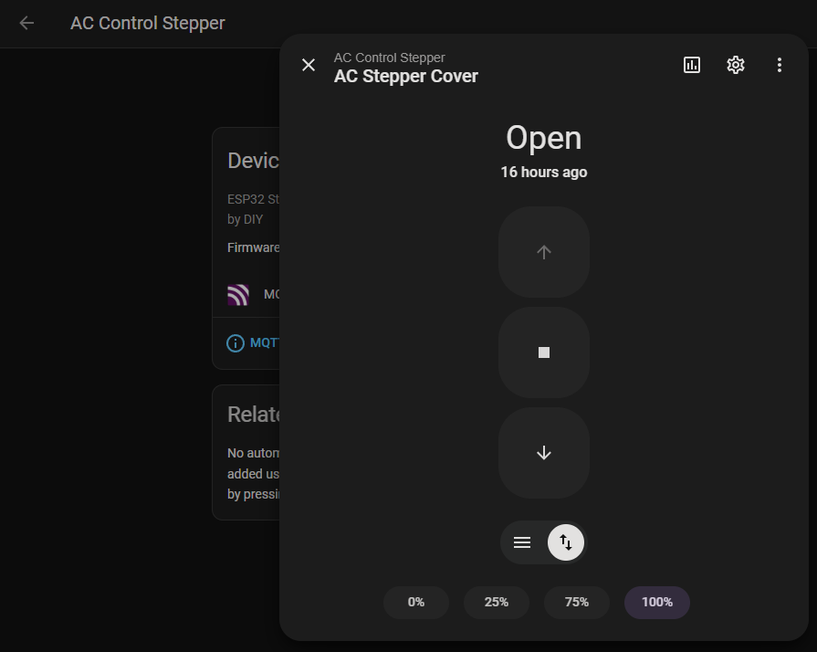
For a dial controller like this, I decided to expose it as an MQTT Cover integration. While “covers” are typically used for things like window blinds, motorized curtains, or garage doors… its schema supports opening, closing, stopping, which maps pretty well to our rotating dial.
When the ESP32 boots up, it automatically connects to the MQTT broker and fires off this discovery JSON payload:
{
  "name": "AC Stepper Cover",
  "unique_id": "ac_stepper_esp32_01",
  "object_id": "ac_stepper_cover",
  "command_topic": "homeassistant/cover/ac_stepper_cover/set",
  "state_topic": "homeassistant/cover/ac_stepper_cover/state",
  "position_topic": "homeassistant/cover/ac_stepper_cover/position",
  "set_position_topic": "homeassistant/cover/ac_stepper_cover/position/set",
  "payload_open": "OPEN",
  "payload_close": "CLOSE",
  "payload_stop": "STOP",
  "device_class": "damper",
  "device": {
    "identifiers": "ac_stepper_esp32",
    "name": "AC Control Stepper"
  }
}
Once Home Assistant registers the cover, it listens for user interaction on the UI and publishes corresponding commands to the command_topic. On the ESP32, the MQTT callback parses the message and drives the stepper motor:
void mqttCallback(char* topic, byte* payload, unsigned int length) {
  String message = extractMessageFromPayload(payload, length);
  if (String(topic) == COMMAND_TOPIC) {
    handleCoverCommand(message);
  }
}

void handleCoverCommand(const String& command) {
  if (command == "OPEN") {
    motorState.isOpening = true;
    moveMotor(STEPS_PER_REVOLUTION, motorState.currentSpeed);
  } else if (command == "CLOSE") {
    motorState.isOpening = false;
    moveMotor(-STEPS_PER_REVOLUTION, motorState.currentSpeed);
  } else if (command == "STOP") {
    stopMotor();
  }
}
Sending an OPEN payload makes the stepper motor rotate forward by a full revolution, wrapping the dial to “Coldest”, while CLOSE spins the stepper backward to turn it off.
And just like that - Home Assistant can control the motor!
Step 2: Adding a Thermostat⌗
With the dial controllable via Home Assistant, the final step was telling it when to turn on and off.
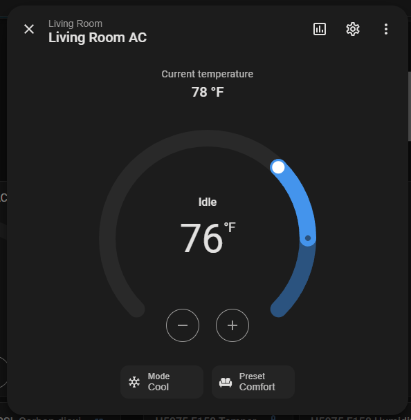
Fortunately, Home Assistant has a built-in integration called Generic Thermostat. It’s dead simple - point it at a switch/cover to toggle + a temperature sensor to monitor, and it handles all the hysteresis logic for you!
For the temperature sensor, I’m using an AirGradient ONE, a high-quality smart air quality monitor that happens to live in the same room as the AC unit.
Hooking the two together is as simple as adding this to my configuration.yaml:
climate:
  - platform: generic_thermostat
    name: Living Room AC
    heater: cover.ac_stepper_cover
    target_sensor: sensor.airgradient_temperature
    min_temp: 65
    max_temp: 80
    ac_mode: true
    cold_tolerance: 0.5
    hot_tolerance: 0.5
And just like that, I had a fully automated smart thermostat running my AC unit!
🛌 Building a Second Unit, Upgrading to V1⌗
Having the living room AC automated was awesome, but as someone who lives in an NYC apartment with the unfathomable luxury of having both a living room and a bedroom - I realized that I’d need to build a second contraption to automate the second, identical AC unit in my bedroom.
Unfortunately, I was fresh out of leftover IKEA brackets and VESA screws… so it was time to find some “real” components I could use to build a more “production-ready” V1 version.
There’s definitely a world where I decided to use this project as an excuse to finally buy a 3D printer and dip my feet into the world of more “serious” hardware engineering… but truth be told - I just wanted to solve my problem ASAP, so my smooth software-engineering brain decided to just KISS.
So I went on a little Temu and Amazon shopping spree, and sourced new parts. Here is the bill of materials for the V1 build:
| Part | Cost | Source |
|---|---|---|
| ESP32 Dev Board (but smaller) | $3.30 | Temu |
| Shaft Coupler | $2.42 | Temu |
| Stepper motor + controllers | $2.66 ($8 / 3 pack) | Amazon |
| L Bracket | $0.50 ($4 / 8 pack) | Amazon |
| Nuts and bolts | negligible4 | Amazon |
| USB cable + charger | $5 | Temu (take your pick) |
| Binder Clip (bodge) | negligible | The Office 🤫 |
Total: ~$14
For V1, I swapped out the bulky ESP32 dev board for a much smaller dev board, and used adjustable metal L-brackets that had slots. This allowed me to bolt the stepper motor directly to the bracket with actual nuts and bolts, making the motor-to-bracket connection rock-solid.
Here is what the finished V1 bracket assembly looks like from various angles:
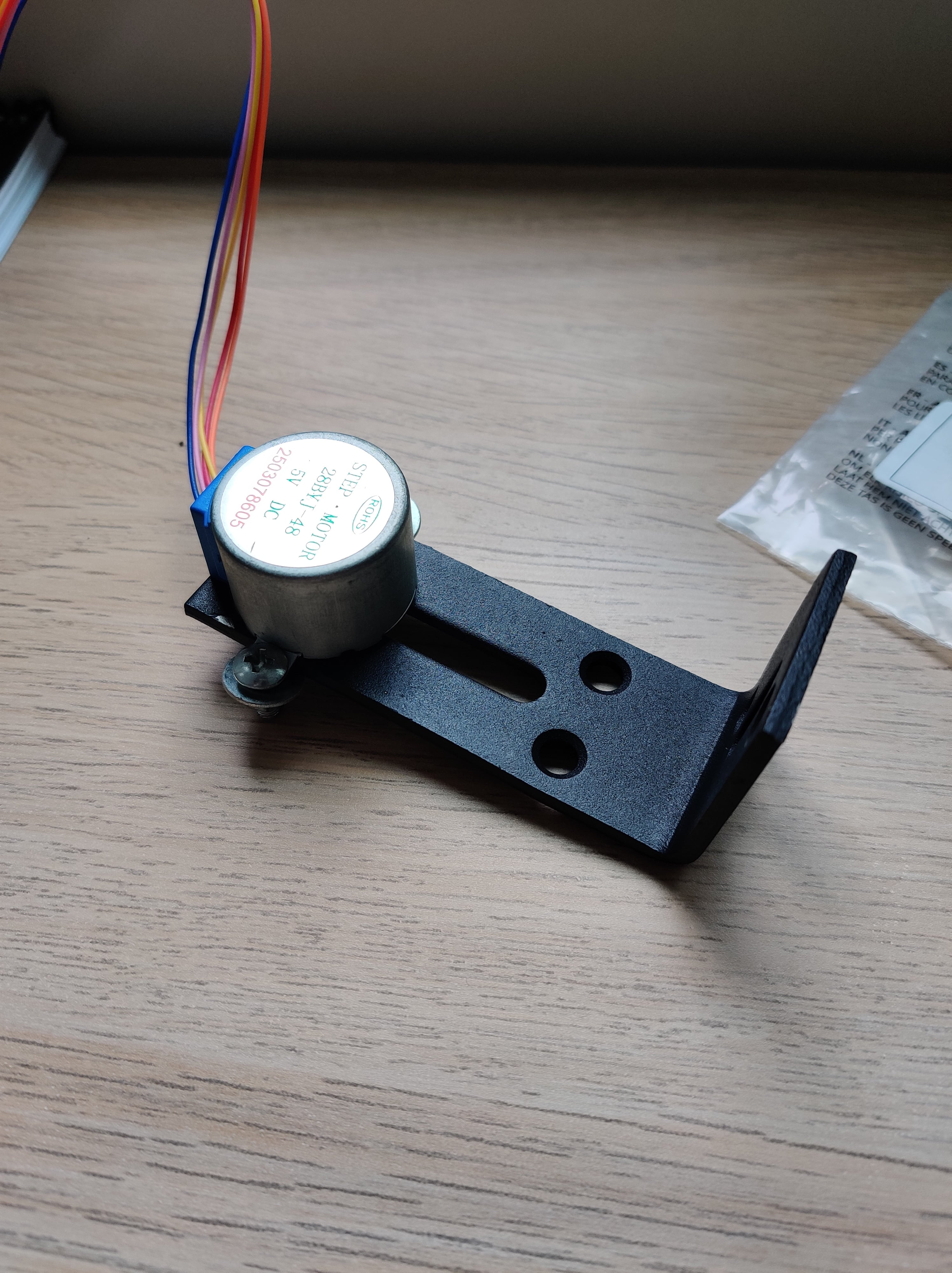
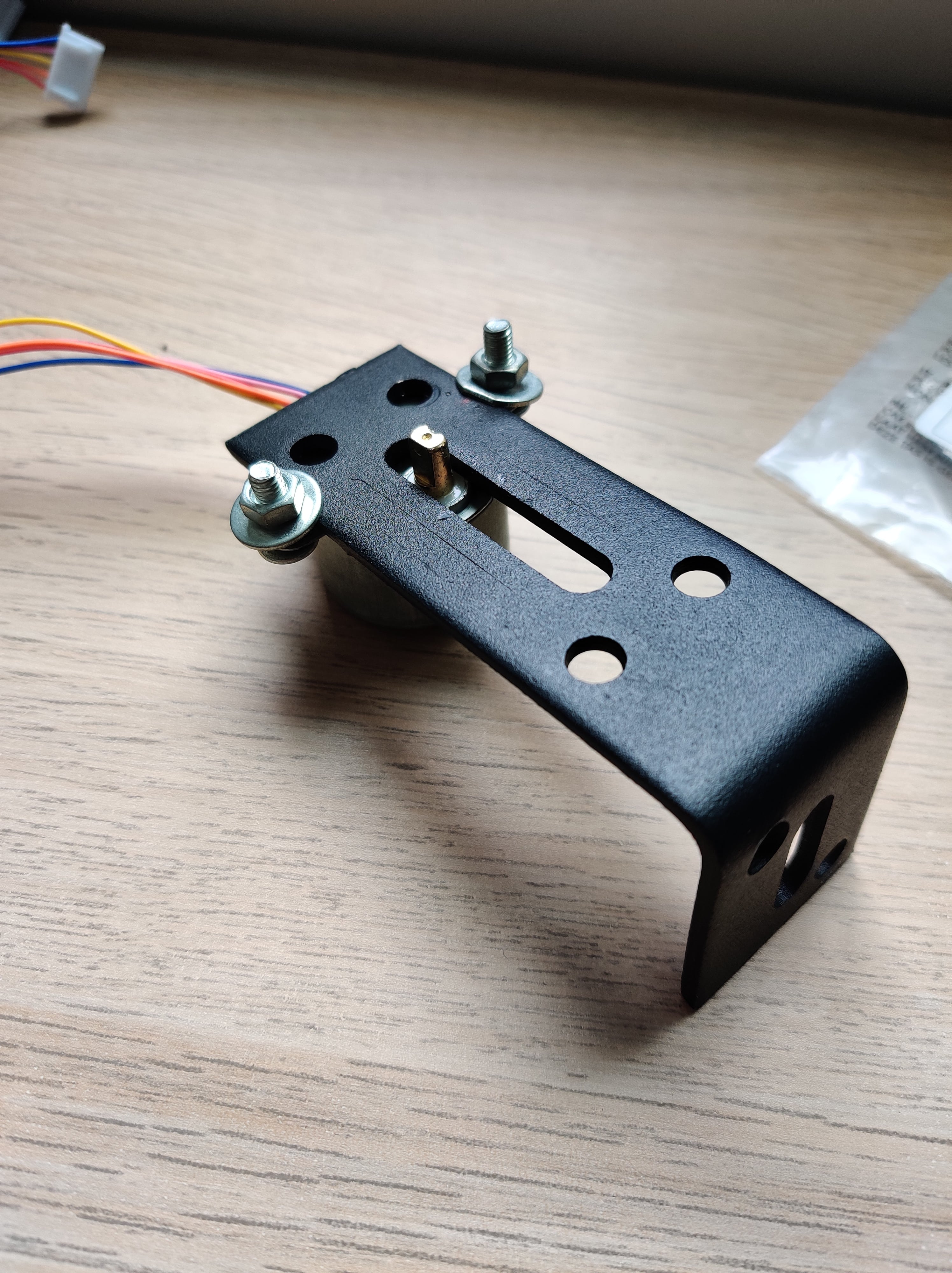
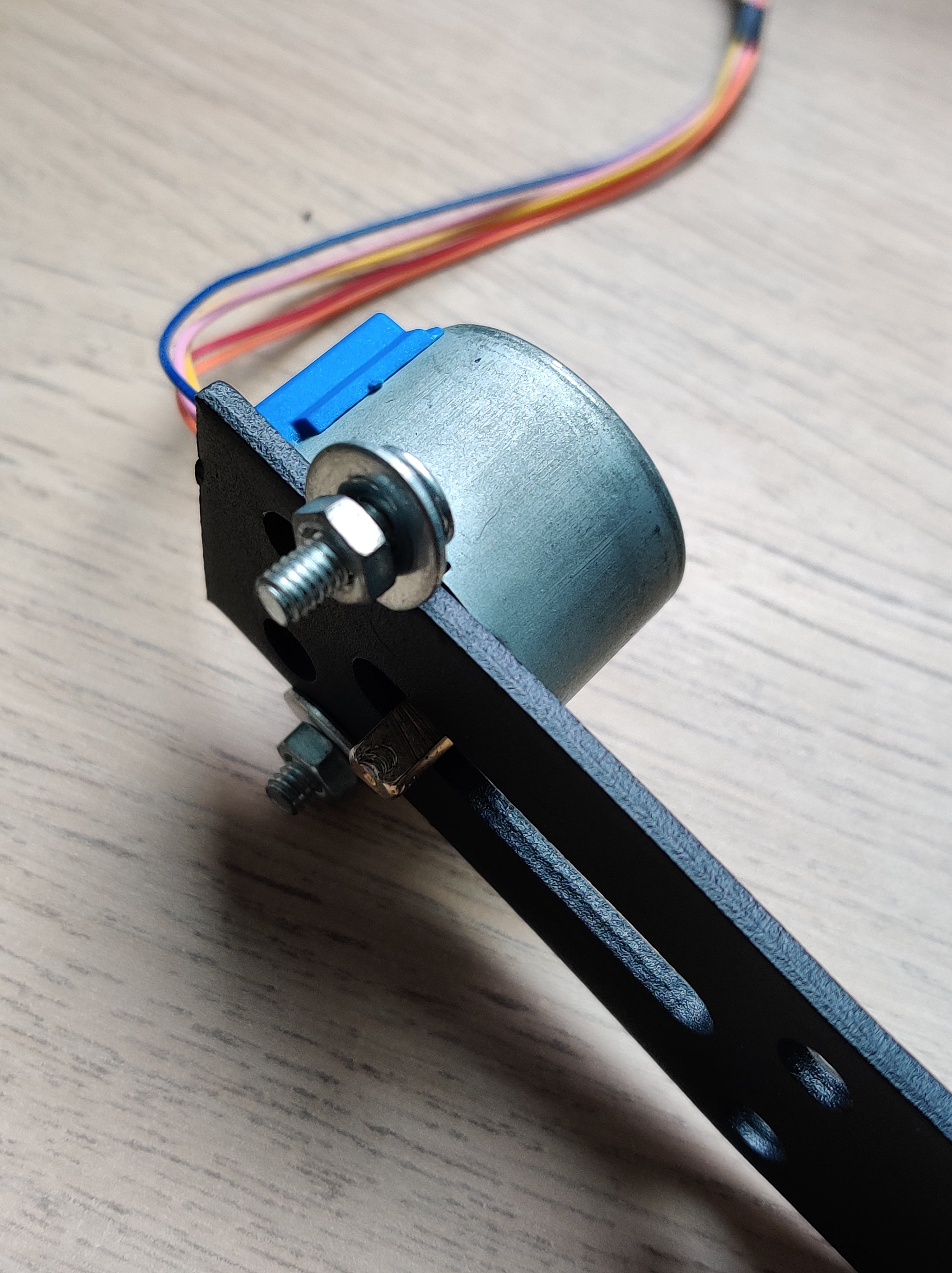
Instead of letting the brackets float and bump against the back wall, I decided to “super securely mount” the assembly to the vertical sheet metal inside the AC’s control compartment using a large binder clip and some “industrial grade” cardboard (to get the spacing just right).
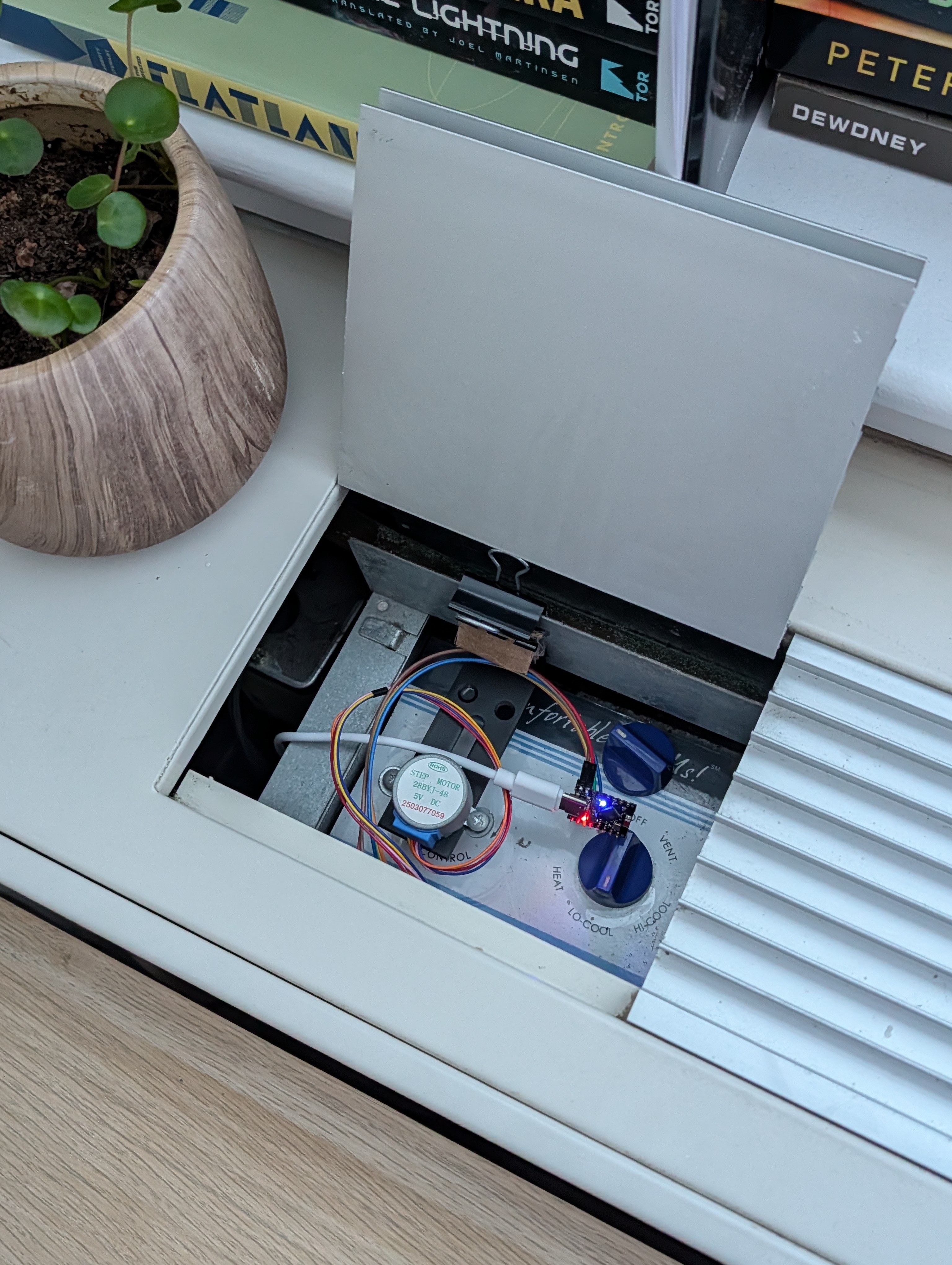
I plugged the small ESP32 board in, tucked it neatly into the compartment, and closed the lid. And thanks to some clever USB cable routing - if you look at the AC unit from the outside, you would never even know it was smart!
📝 Real World Feedback⌗
So funny enough, I actually built this entire assembly last summer, and even wrote ~80% of this blog post shortly after deploying the project… but then I got sidetracked with other stuff, lol.
On the bright side, this means that I’ve had ample time to actually put this project through its paces, and with 1-and-a-half summers under its belt so far, I can safely report the following:
It works okay?
Definitely not great… but maybe ~80% okay?
Ultimately, the biggest issue is that binder clips and cardboard aren’t quite as robust of a mounting mechanism as I’d hoped they’d be… and over time, the stepper motor tends to “sag” a bit, resulting in a bit too much friction between the motor, the coupler, and the underlying knob, causing the mechanism to stall out until someone manually goes and reseats it…
Is this annoying? Yeah.
Is this less annoying than having to constantly adjust the AC manually? Absolutely.
Who knows though? If I’m still in this apartment next summer - maybe I’ll actually invest in a 3D printed mounting solution to bring the reliability up to 100%?
🤔 Final Thoughts⌗
Is it the most elegant piece of mechatronics engineering? Absolutely not.
It’s jank as hell, held together with binder clips, cardboard padding, running slopcode firmware, and built entirely out of cheap parts from China.
But who cares! It solves my hyper-niche problem Well Enough™️, cost me less than $15, and has provably saved me a non-trivial amount of money on my electricity bill.
So at the end of the day, I’m pretty happy with how it all turned out :)
-
oddly specific, I know ↩︎
-
The only real diff between these two modes is how fast the dispersion fan runs. Empirically, hi-cool does make the room cool a bit faster… at the expense of the fan being extra-loud. I usually stick to lo-cool. ↩︎
-
This works thanks to a nice property my unit has: when the target temp has been hit, and no more cooling is needed - the unit goes totally silent and inert (until the temp goes back up, and the unit needs to kick back in) ↩︎
-
It was ~$7 for a pack that’ll last me for years to come ↩︎